|
| Completed CMR 135' Turntable |
This detailed tutorial of
Building The CMR 135' Turntable was published in the March/April 2008 issue of N Scale Magazine.
I always wanted a turntable module on the "Original" JJJ&E when designing the original layout. This module was added to the layout after the mainline track was completed.
I decided to order the CMR 135' turntable after reviewing many articles on this kit. The CMR 135' Turntable was the only highly detailed turntable available in N scale when I built this kit in 2004. Today, Walthers has a ready to run turntable available to the N scale community. However, the CMR turntable kit offers a challenge to those modeler's who want to build a turntable themselves.
I ordered the turntable kit from CMR in Baltimore Maryland. The CMR 135' turntable kit was $115 plus $10 shipping and handling. I was told this kit would take 16-18 hours to build and weather. I was also advised to take my time and not rush building the kit as there were many exacting procedures required to makes this kit run efficiently.
 |
| Photo # 1 Pool Lanai And Enclosure Was My Work Place For Building This Kit |
The morning I started the kit, it was a beautiful day in South Florida I decided to start this project outside on my pool deck in the enclosed pool lanai. The air temperature was 74 degrees Fahrenheit and there was no humidity in the air or threat of a hurricane. The peaceful setting behind the house is an ideal location to build the CMR turntable kit as I'm going to use Tenax-7R/ PlastiStrut to bond the acrylic pieces of the kit together. ( Photo # 1 ). Tenax-7R is highly vaporous and requires good ventilation when using it. I will try and limit my work sessions to one hour daily and scheduled a little over two weeks to complete the turntable.
 |
| Photo # 2 CMR Turntable Kit Came In A Well Constructed Box |
The CMR 135' turntable kit came packaged in a well constructed box. The instructions were very comprehensive and easy to follow. Many kits have poorly written instructions that are difficult to follow without numbered parts. The CMR kit is just the opposite as the instructions are easy to follow with parts that are well documented. ( Photo # 2 ).
 |
| Photo # 3 Acrylic Parts Board |
The parts were placed on two acrylic parts boards. These parts would have to be removed with a heavy-duty Xacto blade due to the thickness of the parts. ( Photo # 3 ).
For additional supplies to start with, you will need an acrylic bonding agent such as Tenax-7R or PlastiStrut, brush applicators and a syringe with different gauge needles to transport the bonding agent to the necessary acrylic parts. You will also need Squadron white putty to fill in any voids in the turntable deck wall and CA cement to bond other acrylic parts.
A heavy duty X-Acto will also be needed to cut out the acrylic parts from the frames of the two parts boards and various rail nippers and craft tools. A small mixing spatula for mixing the Squadron white putty would also be helpful. ( Photo # 4 )
 |
| Photo # 4 Supplies Need To Build CMR Kit |
There are different acrylic bonding agents available on the market to
"bond" the parts in this turntable kit such as Tenax-7R. PlastiStrut has a bonding agent as well. There are also various commercial bonding agents used to build plastic display cases that can also be used.
I decided to use both Tenax-7R and PlastiStrut's bonding agent to test the properties and bonding capabilities of both products for N scale acrylic kits. PlatiStrut's bonding agent cost $5.99 for four ounces. Tenax-7R cost $3.99/ounce. The properties and bonding capability of both Tenax-7R and PlastiStrut's bonding agent are comparable, although the PlastiStrut bonding agent was more cost effective.
The volatility of both bonding agents is very high. The container of each bonding agent shouldn't be left open for any extended period of time as the bonding agents will vaporize and evaporate very quickly. Again, either bonding agent should be used in a well ventilated room or as in my case, outside. One should not inhale the vapors and it might be wise to use a face mask to cover your nose. A pair of latex gloves might also be useful in handling these substances, as they are very reactive and volatile.
I then placed the circular turntable base on a work area and then proceeded to cut the 120 ties needed for the turntable base and rail guide from the parts board. ( There are many extra ties if needed. ) Occasionally, one or two ties will break when removing them from the parts board. This slow work and you should be careful when removing the ties from the parts board.
This took about one hour and fifteen minutes. As I removed each tie section, I smoothed the end of each tie ( the part that was attached to the acrylic parts board ) with a very fine grit sandpaper to remove any flash.
I the placed all the ties securely on the turntable base. Some ties fit easily and others were a very snug fit. Make sure that the ties are
seated firmly in the turntable base.
 |
| Photo # 5 All Ties Seated Firmly In Place On Turntable base. |
Photo # 5 shows the 120 ties seated on the turntable base. They are not bonded in position with the bonding agent as of yet.
 |
| Photo # 6 Closeup Of Ties Seated Firmly In Place |
Photo # 6 shows a closeup photo of the ties seated firmly in place in the base. I contrasted the photo to show the ties in the relationship.to the turntable base. The indented area on each tie shows where the guide rail for the turntable bridge is to be placed.
The next section of this kit deals with bonding the ties onto the turntable base and placing the guide rail on the ties while they are not completely bonded to the turntable base. This isn't as difficult as it might seem.
I used the bonding liquid ( Tenax-7R/PlastiStrut ) to bond the 120 ties to the turntable base. The ties must be
completely seated when you apply the bonding agent to the ties and the turntable base. If the ties aren't completely seated in the turntable base, the guide rail for the turntable bridge wiill not seat properly. If this is the case, the above procedure must be repeated.
As the bonding agent is setting between the ties and the turntable base, you must slide the guide rail through the notch of the 120 ties. At the 180 degree angle, use rail nippers or a saw blade to cut the rail half way around.
Guide the remaining rail through the ties to complete the circle. You now have one rail with two cuts 180 degrees apart. The cuts are about 1/16" wide.
 |
| Photo # 7 Closeup Of The Guide Rail With Cut |
Photo # 7 is a close-up of one of the cuts in the guide rail. At this point in the construction of the turntable, the guide rail must be cemented to the turntable base with some CA cement. I placed CA cement on both sides of the rail at the turntable base in between 120 ties with a common pin as applicator.
I will now let the turntable base harden, undisturbed for the next 24 hours so the bonding agent and CA cement can completely set up. So far, I've been working on this kit for about 2 1/2 hours plus.
Today is another beautiful day in South Florida. It is a bit more humid outside and the temperature is about 82 degrees Fahrenheit, but this is still the best place to work, especially with the "volatile" bonding agent that we must use in constructing this kit.
The turntable base was completely "cured" overnight. It is about 24 hours after I finished working yesterday.
The first thing I did was to use a razor saw and redefine the two cuts I made in the guide rail at 180 degree intervals.
The instructions say to measure two inches to the right of each cut and cut the guide rail again.
This was done for any DCC installation that might be considered. I will hook up a Lenz Reversing Loop Module to these two wires in the two inch cuts that I made. This will change the polarity for me when the turntable is fully operational and motorized.
I then proceeded to drill four holes in the areas of the two-inch cuts and other cuts for the wiring to the guide rail.
 |
| Photo # 8 22 Gauge Wire Used For Electrical Connections |
 |
| Photo # 9 Closeup Of 22 Gauge Wire Soldered To The Guide Rail |
( Photo's # 8 & # 9 ) After the four holes were drilled to the turntable base, I used 22 gauge wire for the electrical connections. I bent the wire at approximately right angle, tinned the wire and rails and soldered the 22 gauge wire to the guide rail in the turntable base ( using red and black wiring ).
 |
| Photo # 10 Closeup of 22 Gauge Red Wire Soldered To Guide Rail With Hako Soldering Unit |
( Photo # 10 ) Here is a close of the wiring. There is little room to work and tinning the guide rail and 22 gauge wirehelps immensely before you solder. You should use a soldering station with a very fine electronic soldering tip. I have a Hako soldering station that is digitally controlled. The electronic soldering tip is primarily used when soldering circuit boards. I use this electronic tip all the time for soldering in N scale, especially when I'm working on decoders for DCC control.
The next step is to build the pit wall. You must remove all necessary parts from the parts board.. The 1/16" parts have to be removed carefully as they are quite thin. I broke one of the pieces, but it was not a problem.
You can build the pit wall directly on the turntable base or you can build it apart from the base and cement the final pit wall to the base of the turntable.
( Photo # 8 ) I chose to build the pit wall directly to the base. I used some very fine sandpaper to smooth down any irregularities in the pit wall structure. Then I proceeded to build the pit wall, layer by layer, using the bonding agent after each layer. The wall must be lined up perfectly or else the bridge will interfere when it rotates. There is a scribed line on the turntable base to follow to get the correct position of the pit wall to the base.
The final height of the pit wall is about 10/16". The pit wall must be coursed like brick for strength. To accomplish this, overlap the starting point from one layer to the next. The final two layers are lipped, which should be raised enough for most roadbeds of the track to the turntable.
 |
| Photo # 11 Screwdriver Blade Gives Some Perspective On The Height Of The Turntable Pit Wall |
Photo # 11 will give you some perspective about the depth of the turntable pit to the turntable wall. I used a small screwdriver blade that I placed at the bottom of the pit to show the perspective.
At this point in the CMR 135' turntable kit construction, I will let the walls of the turntable cure 24 hours before continuing. The walls of the turntable were bonded to the turntable pit with Tenax-7R/PlastStrut bonding agent.
The next step is to construct the turntable bridge. I'm about 4+ hours into the construction of the CMR 135' turntable.
The next morning, it was time to start building the turntable bridge. The bridge parts were removed carefully from the parts board. I bonded the interior braces individually, which keep the bridge girders properly spaced apart.
 |
| Photo # 12 Braces Guided to The Bridge Girder |
 |
| Photo # 13 Braces Bonded To Bridge Girders |
( Photos #12 & # 13 ) There is a scribed line on the girder to show the position of each interior brace. Once one complete set of braces was bonded to the bridge girder, I bonded the interior braces to the second bridge girder. The interior braces must be properly aligned and kept square to the girders.
after the initial set, I proceeded to glue the exterior ribs to the girder using CA cement. The exterior ribs were made out of a hard paper product. I think these exterior ribs should have been made out of acrylic as well. There are also other detail parts that are also made of this hard paper product. These should also have been made in acrylic for strength. If a kit of this magnitude is to be built, all parts of the substructure should have been made in acrylic and not hard paper for the obvious reason stated above. ( Photo # 12 ).
The next step is to add the track rails to the bridge platform and to fabricate the wheel assemblies and wire the wheel assemblies underneath the bridge.
So far, this project has taken six hours up to this point.
I will also add Squadron putty to the interior walls of the pit to remove any imperfections in the acrylic wall. I will closely examine the acrylic wall with some magnifying loops to see if I have putty the interior walls of the pit. I will use Squadron white putty for this step if necessary.
The nest step in the construction of the CMR turntable is to add the bridge deck for the track to the bridge girders.
The deck has to be snapped in place on the bridge girders in four places. Two didn't line up properly and that is a common experience according to the instructions. I then used a fine file to slightly shorten the male connectors of the bridge girders. Once accomplished, the deck snapped in position and I bonded the deck to the bridge girders with the bonding agent.
I then placed the two rails in position on the deck. There are small grooves that show you the exact rail placement. The rails were cemented in position with CA cement. As the cement was setting, I checked the rails with a track gauge to make sure the rails were in proper gauge. I made a few adjustments at this time and I placed two gauge "spacers" on the rails, which were provided with the kit.
 |
| Photo # 14 Evergreen Strips Added Along Walk Ways For Additional Support |
I modified the kit slightly by adding Evergreen strips along both walkways. After the bridge is airbrushed and weathered, I will add the detailed heavy paper walkways on top of the Evergreen strips. There is also a detailed strip to place between the rails of the bridge ( Photo # 14 ).
I also added about 3/4 ounce of lead weight to each end of the bridge assembly, so that the wheel assemblies on each end will make proper contact with the guide rail below on the pit floor. I used A-Line lead weights for the necessary weight at each end of the bridge assembly ( Photo # 15 ).
 |
| Photo # 15 A-Line Weights Added To End Of Bridge Assembly |
The bridge itself was nicely weighted with the addition of lead weights and will allow the bridge roller contacts to make contact with the pit guide rail.
You can see the bridge trucks at each end of the bridge assembly. The wheel assemblies will be attached to the bridge trucks. There are four wheel assemblies and I was missing one, so the missing assembly is being mailed to me ( Photo # 22 ). I tapped three of the wheels into each brass axle in the meantime.
 |
| Photo # 22 Wheel Assemblies For The Bridge trucks |
I will probably start to airbrush the bridge of the turntable a grimy balck while waiting for the fourth wheel assembly.
At this point, I decided to putty the inside wall of the turntable pit with Squadron white putty using a small dental mixing spatula. This was done to smooth out any irregularities in the turntable pit wall.. I'll let the putty dry overnight to completely harden it and then smooth the puttied walls with various grades of very fine sandpaper. I didn't take a photo of the unfinished puttied wall of the turntable. Its now been eight hours since the walls of the pit were smoothed with putty.. The pit is finished except for the smoothing of the pit wall. The bridge of the turntable is almost finished. I have to add the wheel assemblies and wire them.
I then must build the center shaft assembly for the bridge and add a center arch to the bridge as well as a cab control house.
You must be careful to remove enough of the putty to allow the bridge to turn freely in the pit. The bridge has to be placed in the pit to make sure the Squadron putty added to the pit wall doesn't impinge on the movement of the bridge deck ( Photo # 16 ).
 |
| Photo # 16 Bridge Deck Seated Inside Of Turntable Pit To Make Sure It Turns Freely |
 |
| Photo # 17 Center Of Bridge Assembly Seated On Turntable Pit Floor |
In Photo # 17, you can see the center of the bridge assembly resting on the turntable pit floor.
The Evergreen strips are support for the detailed heavy paper walkway that will be added to deck after it is airbrushed and weathered. This was a modification from the original instructions as the heavy paper walkway isn't strong enough by itself.
 |
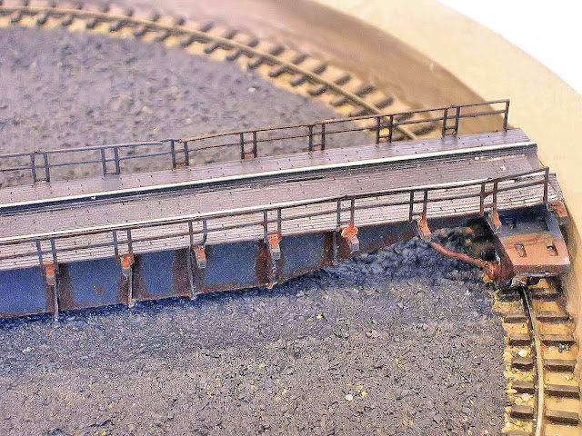
| Photo # 18 Relationship Of The End Of Bridge To Turntable Deck |
Photo # 18 shows the end of the bridge deck and its relationship to the turntable deck. The bridge deck will be shimmed slightly, once the wheel assemblies are put in place so that the bridge is level with the top of the turntable pit.
 |
| Photo # 19 Closeup Of Lead Weights At End Of Bridge Assembly |
 |
| Photo # 20 Closeup Of Lead Weights At End Of Bridge Assembly |
Photos #19 & #20 are both close-up magnifications showing the placement of the lead weights at the end of the bridge assemblies. This will provide the wheel assemblies with more weight to contact the guide rail in the turntable pit.
Next, I airbrushed the bridge deck of the CMR 135' turntable kit a grimy black ( Photo # 21 ).
 |
| Photo # 21 Turntable Bridge Deck Airbrushed A Grimy Black |
When the bridge deck is dry, I will airbrush a wash of earth, dust and Blue Windshield Wiper solution on the bridge to create a thin layer of dust and grime. I use a wash of 80% blue windshield wiper solution and 20% acrylic paint for all my individual wash.
When that wash has dried, I will dry brush different layers of rust and dirt deposits near the exterior ribs and other parts of the bridge deck.
Next I will airbrush the pit with a primer and then used aged concrete as the final color.
I also plan to build the center shaft assembly and fit that to the bridge deck once I have the fourth wheel assembly in hand. I will also add the heavy paper detail parts to the walkways once the wheel assemblies and wiring is completed.
When I built this kit, I was missing one of the wheel assemblies from the original parts list. I contacted CMR and they sent me several replacement wheel assemblies. I soldered the wiring to the wheel assembly on three of the four-wheel units ( Photo # 22 ).
|
| Photo # 22 Wheel Units For The Wheel Assembly. |
You must tap the wheel through the axle on each wheel assembly to firmly engage the wheel in the axle. I used the wire that CMR supplied in the kit to solder two wheel assemblies together electrically. The joint in the middle will lead to one of the rails and the other will go to the opposite rail. I only have one axle support on each assembly. When I'm ready to anchor the completed assembly, I'll attach the axle supports that are missing.
 |
| Photo # 23 Detailed Heavy paper Walkways Added To Evergreen Strip Supports |
( Photo # 23 ) I then added the detailed heavy paper walkways to the Evergreen strip supports That I added to the bridge deck. ( Photo # 24 ) I painted the turntable pit an aged concrete. When the pit was dry, I made a wash of blue windshield wiper solution, mud, earth and dust and airbrushed athin wash on the turntable.
 |
| Photo # 24 Turntable Pit Painted An Aged Concrete |
I also hand painted all 120 rail ties a Polly Scale Rail Tie Brown. All the edges of the ties had to hand painted as well. I used an 18/0 very fine sable brush to paint the edges of the ties. This took considerable time to do.
Then I made a wash of Engine Power Black and blue windshield wiper solution. I sprayed the wash on the turntable pit to create an aged effect.
( Photo # 24 ) When all these washes dried, I used some very fine natural ballast and spread the ballast on the bottom of the pit and cemented the ballast in place with a mixture of Aileene's white glue and iso-propyl alcohol. I used an eye dropper to apply the cement to the ballast on the base of the turntable pit. Using an eye dropper to apply the glue/alcohol mix keeps the ballast in position. It takes longer to glue the ballast using this procedure, but in the long run, the ballast will remain in its original position.
I also weathered the bridge deck of the turntable. I used the thin wash of blue windshield wiper solution with mud, earth and dust and lightly airbrushed the bridge to create a dulling and weathered effect on the paint.
When these washes dried, I detailed the exterior ribs and the bridge deck girders with Burnt Umber, and Burnt Sienna to simulate a well rusted structure ( Photo's # 25, # 26, # 27 & # 27A ).
 |
| Photo # 25 Detailed and Weathered Bridge Deck |
 |
| Photo # 26 Detailed and Weathered Bridge Deck |
 |
| Photo # 27 Detailed and Weathered Bridge Deck |
 |
| Photo # 27A Detailed and Weathered Bridge Deck |
I still have more to finish on the turntable. The wheel assemblies have to be shimmed and cemented in place after the final wiring to both rails is completed.
The arch of the bridge deck has to be added as well as the hand rails on the bridge deck. The center shaft assembly also has to be cemented in place.The control cab for the bridge has to be built as well.
When the wheel assemblies are shimmed to the proper height, there will be enough clearance to compensate for the fine ballast I added to the pit base.
This has been a great kit to build as long as you proceed slowly and follow the directions in the instruction manual. I highly recommend this kit if you are interested in building a quality turntable for your layout. The CMR turntable kit also comes in a 105' length as well.
Next I added the wheel assemblies to the underside of the turntable bridge. The wheels turn easily because of bearings that are incorporated in its design. I used a shim to raise the bridge to accommodate the Unitrack that I'll be using from the edge of the turntable pit to the Roundhouse stalls. I also wired the wheel assemblies to the bridge rails ( Photo # 28 ).
 |
| Photo # 28 Wheel Assemblies Wired To Bridge Guide Rails |
I painted the walkways on either side of the bridge deck a Railroad Tie Brown. I will weather the bridge deck walkways once I have the handrails, arch and arch supports cemented in place. I airbrushed the natural rock ballast I added to the pit floor a grimy black to simulate cinders in the pit floor ( Photo # 29 ).
 |
| Photo # 29 Ballast Painted A Grimy Black To Simulate Cinders On Pit Floor |
I let the new "cinder" base in the turntable pit completely dry and harden for 24 hours. Then I checked the bridge deck and wheel assemblies to make sure they were resting on the guide rail throughout the 360 degree circle ( Photo # 30 ).
 |
| Photo # 30 Bridge Deck Placed On Turntable Pit Floor To Check Wheel Assemblies |
( Photo # 31 ) Here is a closeup of the right wheel assembly on the turntable pit floor.
 |
| Photo # 31 Closeup Of Right Wheel Assembly Resting On The Turntable Guide Rail |
Now the center shaft assembly will be glued in position after the turntable arch, arch braces and handrails are cemented in place on the bridge deck. ( Photo # 32 ).
 |
| Photo # 32 Bridge Deck Center Shaft Assembly |
Here is a photo of the center shaft assembly from the CMR instruction manual. This will attach to an Indexing motor that will drive the turntable bridge ( Photo # 33 0.
 |
| Photo # 33 Photo Of Center Shaft Assembly |
I will add a stationary decoder to control the motor as I can use the Lenz LH 100 handheld of a Lenz 100 system to control the turntable's movement.
I then mounted the stock arch that came with the CMR kit and really wasn't happy with the way it looked.
I was able to find a cast metal Diamond Scale Arch at my LHS which looked much better than the plastic arch that came with the CMR kit. The cost of the Diamond Cast metal scale arch was $4.99. This "find" was located in a spare parts box at my LHS.
I assembled the Diamond Scale Arch for the turntable and cemented it to
the walkway of the bridge deck I gave the bridge deck an initial coat of
grimy black paint and will touch up the first coat with a second coat
of grimy black paint.. After both coats of paint are dried , I'll detail
the Bridge Deck and Arch with Burnt Umber and Burnt Sienna to make the
deck and arch look aged and rusty.
Photos # 34, # 35 & # 36 show the arch in position. I have to bend the arch in a more upright position. Still to be done is the hand railings on the bridge deck, the control cab on the bridge deck and some additional weathering of the deck walkways and arch. I added the control cab to the end of the bridge deck, hand rails, and I did do some additional weathering of the bridge deck arch, the deck girders, the cab control, the handrails, the walkways, the wheel assemblies and connecting power wires.
 |
| Photo # 34 Detailed And Weathered Bridge Deck Arch |
 |
| Photo # 35 Detailed And Weathered Bridge Deck Arch |
In Review:
I used Burnt Umber and Burnt Sienna for the rust effect on the Bridge Deck and Arch. The bridge deck and arch was given a wash of 80% blue windshield wiper solution and 20 % of the three earth tones of Dust, Mud and Earth.
The turntable pit was weathered with a mix of 80 % blue windshield wiper solution and 20 % Grimy Black.
The pit floor was weathered with Grimy Black, and very fine natural rock ballast to simulate cinders.
The ties in the guide rail on the turntable pit floor were weathered with Rail Tie Brown.
The walkways were weathered with some Rail Tie Brown, Reefer White and Dull Aluminum. I mixed the Reefer White and Dull Aluminum together to mute the two colors.
The Arch was mainly weathered with Grimy Black, Burnt Umber and Burnt Sienna. The lights were painted silver.
The Bridge Deck Handrails were weathered with Grimy Black, Burnt Umber and Burnt Sienna ( Photos # 36, #37 , # 38 & # 39 ).
 |
| Photo # 36 Finished Turntable Bridge Deck And Arch |
 |
| Photo # 37 Finished Right Wheel Assembly Of Bridge Deck |
 |
| Photo # 38 Finished Left Wheel Assembly Of Bridge Deck And Cab Control |
|
| Photo # 39 Finished Bridge Deck WalkWays |
The 135' turntable now has to be installed on the 'Original" JJJ&E. I have a 3' x 5' space set aside for this turntable module which will be adjacent to the Switching Yard and mainline of the "Original" JJJ&E. Photo's # 40 & # 41 shows a ATSF #1790 articulated Mallet on the turntable before it was installed on the layout.
 |
| Photo # 40 ATSF # 1790 Articulated mallet On Turntable Bridge |
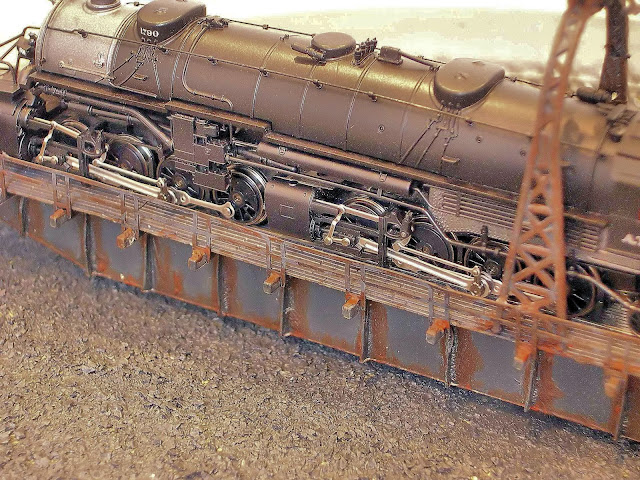 |
| Photo # 41 Closeup Of ATSF # 1790 Articulated Mallet On Turntable Bridge |
Photo's # 42 & # 43 shows a Southern 4-8-2 "Light Mountain on the turntable before it was installed on the layout.
 |
| Photo # 42 Southern # 1401 4-8-2 "Light Mountain" On Turntable Bridge |
 |
| Photo # 43 Closeup Of Southern #1401 4-8-2 "Light Mountain" On Turntable Bridge. |
The CMT 135' Turntable will easily hold the new Athearn 4-6-6-4 "Challenger".
( Photos # 44 & # 45 ) The turntable has been placed on the turntable module of the "Original" JJJ&E adjacent to the Switching Yard.
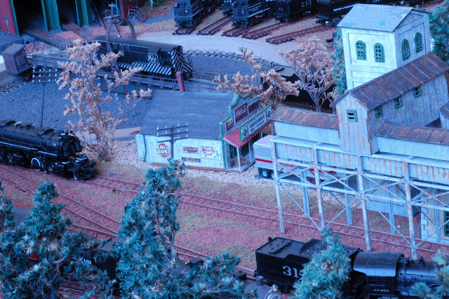 |
| Photo # 44 Finished Turntable On The "Original" JJJ&E |
 |
| Photo # 45 Finished Turntable On The "Original" JJJ&E |
This is a well thought out kit with instructions that are easy to follow. It will take between 14 to 16 hours to finish and weather. The CMR 135' turntable will become the focal point of any layout.
Have fun with it.
Stay cool and run steam.........